LED video walls shape the look and feel of today’s concerts, immersive experiences, and broadcast environments.
Vectorworks Spotlight 2026 introduces the LED Video Wall tool to help you design nearly any wall shape, connect it to real panel data, and generate the reports you need for production.
This article follows the “LED Video Walls – Getting Started” learning path on Vectorworks University and walks you through using the tool, from initial drawing mode choices to panel selection, supports, and content mapping.
Starting with the LED Video Wall Tool
The LED Video Wall tool brings geometry, panel information, support systems, and screen content together in a single parametric object. You can draw the wall in 2D or 3D, assign manufacturer panels, and let Vectorworks Spotlight keep track of sizes, counts, and technical data in the background.
Because the tool lives inside Vectorworks Spotlight, your video walls sit in context with lighting, rigging, scenic elements, and venue geometry. That shared environment gives you a consistent representation for conceptual views, technical drawings, and downstream reports that support production teams.
Choosing How to Draw: Freeform, Aspect Ratio, and Builder
When you go to the Audio Video toolset and activate the LED Video Wall tool, you’ll see three main drawing modes: Freeform, Aspect Ratio, and Builder.
Your choice here depends on whether you’re exploring ideas or working toward a specific hardware layout:
- Freeform mode suits early concepting. In a Top/Plan view, you choose a vertex draw mode, set a wall height, and sketch the outline of your wall, switching vertex types when you want straight segments or curved sections.
- Aspect Ratio comes into play when the wall must follow a specific ratio, such as 16:9 or 21:9. You enter the ratio into the Mode bar, then draw, and the wall grows in discrete steps that preserve the ratio as you drag.
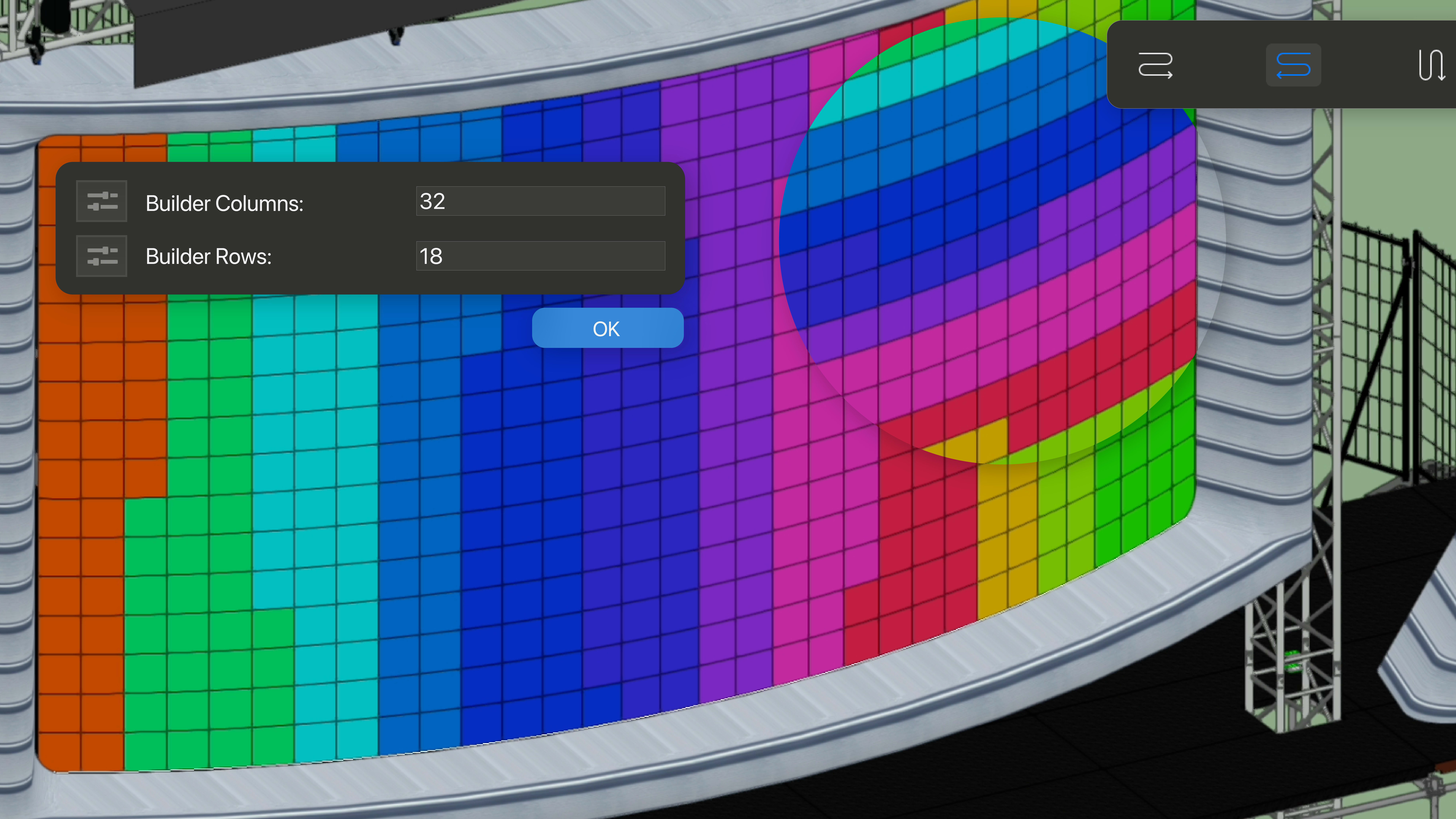
- Builder mode starts from panels rather than an abstract surface. After you define the number of panel columns and rows, the tool uses a default panel symbol to create a wall with fixed dimensions based on that grid.
Using Specialized Drawing Modes
Beyond the three primary approaches, the LED Video Wall tool also includes specialized draw modes that address common design patterns. These modes help you center walls, build circular screens, and create floors or angled planes while keeping the workflow familiar.
Center Out modes let you draw from the center of the wall instead of from a corner. When you combine this with Freeform mode and turn on a Generic Panel Preview in the tool preferences, the wall mirrors itself as you draw and snaps in increments of a panel width that you specify.
Circular draw modes give you a straightforward way to create rings or arcs. You can sketch a circle and decide whether video content should play to the inside or the outside of the resulting surface, which is ideal for immersive environments and in-the-round stages.
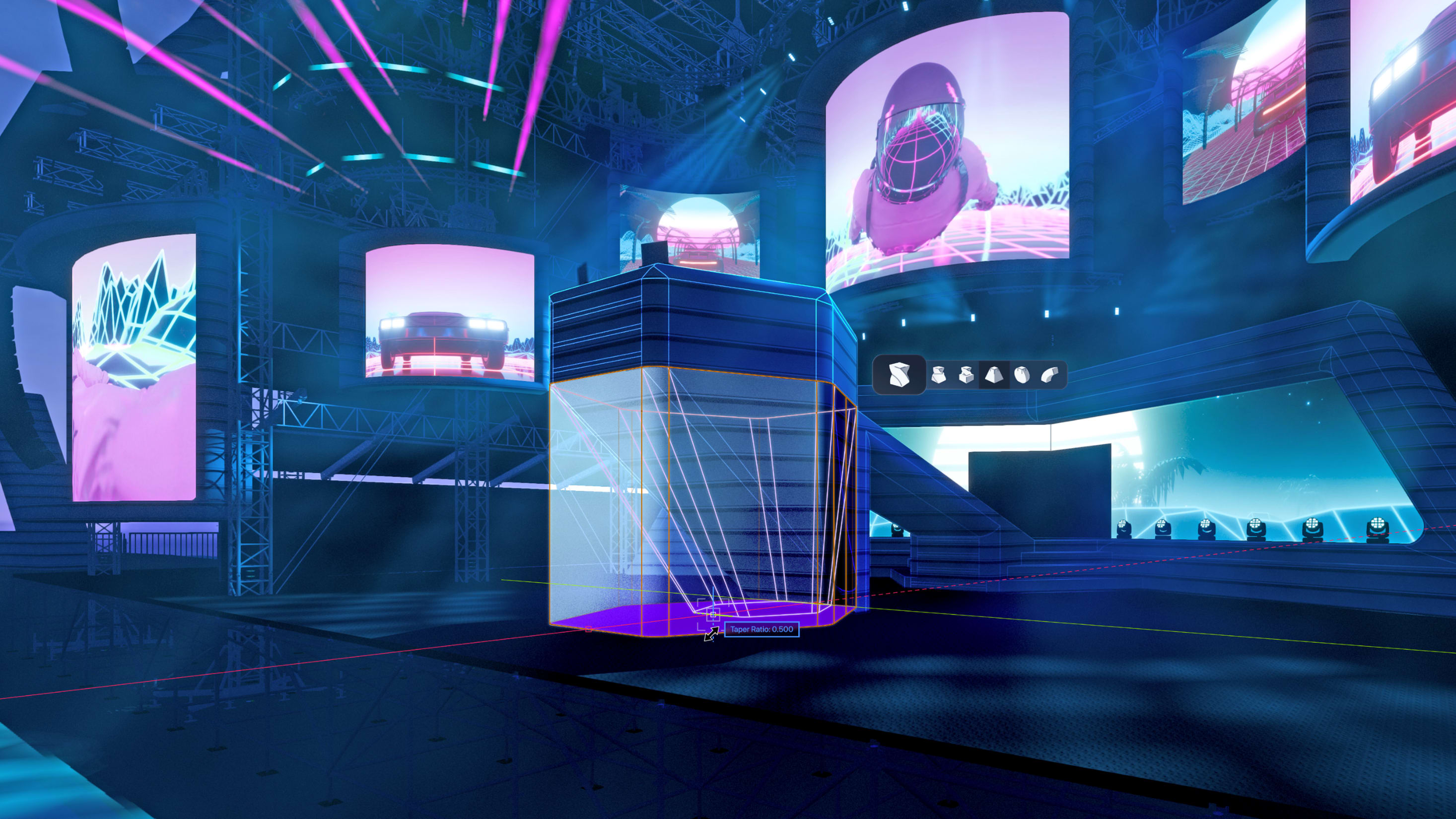
Rectangular mode converts a drawn rectangle into a video wall or LED floor. You can work on the current layer plane for flat floors or set a custom working plane for raked or angled surfaces, which simplifies the creation of dance floors and tilted screens that still behave as LED walls in your documentation.
Turning Concepts into Panel-Based Designs
Panel choice is one of the most important steps in turning a conceptual wall into something that can be built at a venue.
From the LED Video Wall tool preferences, the Panels tab lets you pick a primary panel symbol from the library and, when needed, perimeter panels for the edges. The dialog shows key technical information pulled from the manufacturer’s specifications, so you’re always working with accurate data.
Flat non-segmented panels, such as typical carbon fiber tiles, support angled connections between panels but remain rigid themselves. In the Classes and Attributes pane, you can set concave and convex joint limits in degrees, matching the panel’s spec sheet. The drawing preview then shows panel geometry and increments wall length in panel-sized steps so you can add corners while keeping to allowable angles.
For true curves, you choose segmented or infinite panels like flexible curtain products. In these cases, the wall can form smooth arcs, and the tool continues to grow the wall based on the segment dimensions of the panel you’ve selected.
Lastly, perimeter panels give you a way to close gaps when the wall size doesn’t divide evenly by the main panel width or height, and the preview updates to show how those perimeter pieces affect the final outline.
Adding Ground and Top Supports
With the wall geometry and panels defined, you can then address your structure. The Wall Support section in your preferences lets you specify whether the wall is ground supported or top supported, apply height offsets, and choose support symbols from content libraries. As you pick supports, their specs appear in the dialog, and the preview updates to include both panels and supports.
When you draw a wall onto a truss, top supports such as clamps and drops automatically align to the truss chords, and the panel array shifts to match. If you add supports later, the wall adjusts to keep that alignment consistent.
Ground supports work similarly, pushing the panels up to sit correctly on the frames and updating the wall when you introduce new ground hardware. This gives you a clearer picture of how the wall will sit in the rig and provides more useful information for rigging and staging teams.
Mapping Images and Video Content
Content is what turns your LED wall into a device for immersive storytelling.
New walls start with a simple placeholder image so you can read scale and composition immediately, but switching to your own media is quick. In the Object Info palette (OIP), the Image Settings section lets you choose an image resource, scale it to fill the wall, rotate it, and adjust horizontal or vertical offsets. You can also decide whether the image should tile or stretch, which is useful when testing repeating patterns.
When you want video playback rather than a still, you can move into the Visualization section of the LED Video Wall preferences. There, you’re able to assign a video file and control how it plays on the wall.
Once content is mapped, you can explore camera views, renderings, and live previsualization (previz) with Showcase. With the previz feature, you can evaluate how your media will impact your audience directly inside your Vectorworks Spotlight file.
With these steps, you can move from a blank Vectorworks Spotlight file to a fully specified LED video wall that looks right in previz and carries the technical data needed on site. The LED Video Wall tool in Vectorworks Spotlight 2026 is built to support that complete journey so you can focus on crafting the experiences your audiences remember.
SEE LED VIDEO WALLS IN ACTION
WATCH NOWStay in the know with the latest insights
Subscribers receive news, customer stories, success and learning tips, event information, and other important announcements from Vectorworks.
By submitting this form, you agree that Vectorworks, Inc. and its authorized partners may contact you in regards to news, offers, and the use of our software, services, and platforms. Learn more about our privacy practices and your data on our privacy page.*