Power planning is becoming an increasingly important part of show and event production processes. From calculating the total power needed to creating detailed documentation for site crews and securing venue sign-off, it affects every stage of design and production.
Let’s look at how you can get more out of the cable and power planning features in Vectorworks Spotlight.
What is Power Planning?
Before we discuss features that will improve your power planning workflows, let’s review power planning for shows and live events.
Power planning is the process of designing, organizing, and documenting how electrical power is distributed throughout a show or event production. It involves calculating total power requirements, determining how power flows between devices, and creating detailed plans that help you determine if every fixture, breakout, and distribution point is connected.
Effective power planning helps production teams maintain safety, efficiency, and reliability from design through on-site installation and venue approval.
Cable Drawing in Vectorworks Spotlight for Power Planning
When starting your cable drawings, familiarizing yourself with Vectorworks Spotlight’s suite of cable features can increase your power planning speed.
You can use Patching by Command — either power patch by selection or position — to connect cables and lights to breakouts in seconds. Also known as “squids,” breakouts are the ends of multi-core cables that are used to run as few cables as possible. These cables also usefully follow the truss path between the breakouts and lights.
In your Cable tool preferences, turn on the Automatically Create Cable option. Once you’ve created the cables this way, you can use the Power Schematic feature to repatch them and quickly change the breakout circuit assignment.

Additionally, the Cable tool’s Schematic Distributor mode does more than just cable lights to breakouts. You can also use it to connect breakouts to dimmers and moving light distributions. If your breakouts sit on a truss system, click the truss before connecting the first breakout.

It’s recommended to set an application default cable set before you start drawing. Cable sets control the cables available to the cable types and lengths in your file. Choosing the correct set will save you a lot of time editing cable run configurations later.
If you plan to use the Fewest Parts Option cable configuration option, set the fewest parts to the longest length increment in your cable set. For example, if you’re using the default metric, set it to 10 meters or 20 meters. This setting helps you make sure the configuration jumps up to the next longest cable part correctly.

Lastly, when you work with cables from several companies or rental houses, it’s best practice to create cable sets for each grouping of cables. Then, use the Cable Areas tool to assign cable sets to different drawing layers. For example, you can assign the audio cable set to the audio layer. If you need cable parts not included in the library, duplicate and edit an existing part, then save it into your User or Workgroup library.
Power Schematics in Vectorworks Spotlight for Power Planning
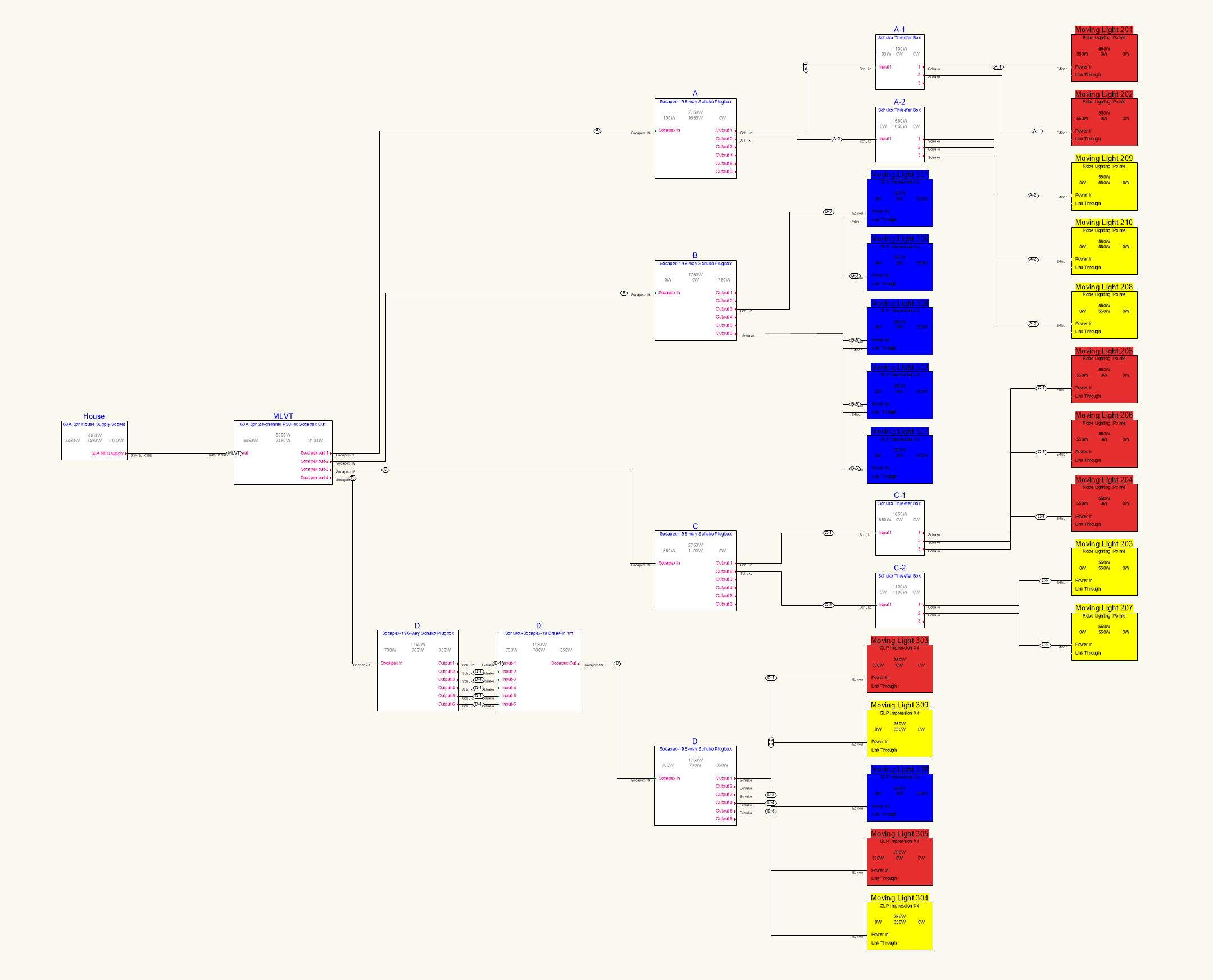
Now, let’s look at ways to get more out of power schematics. Power schematics help your power planning process by giving you an easy-to-read, diagrammatic overview of the power and how it's laid out.
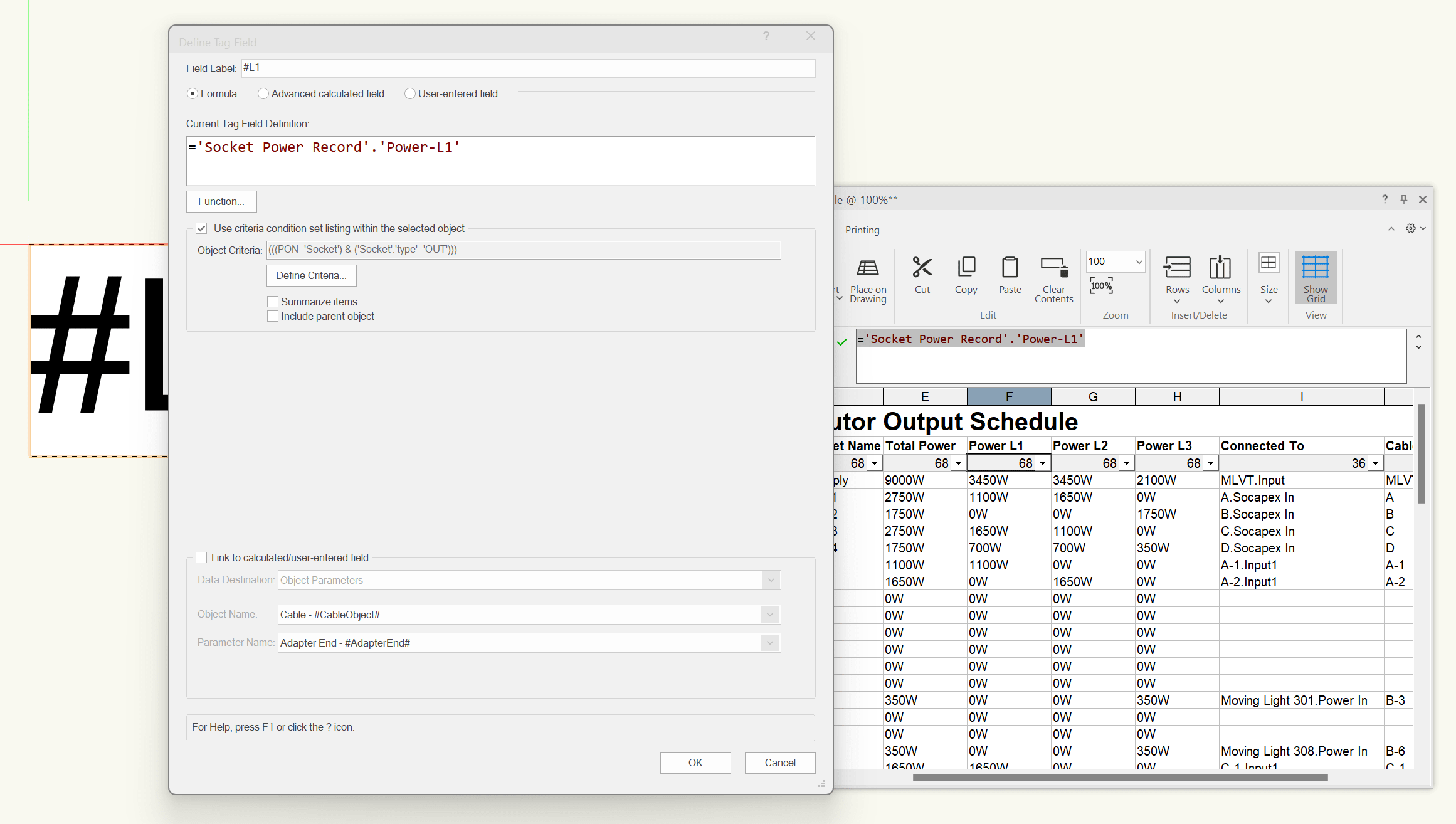
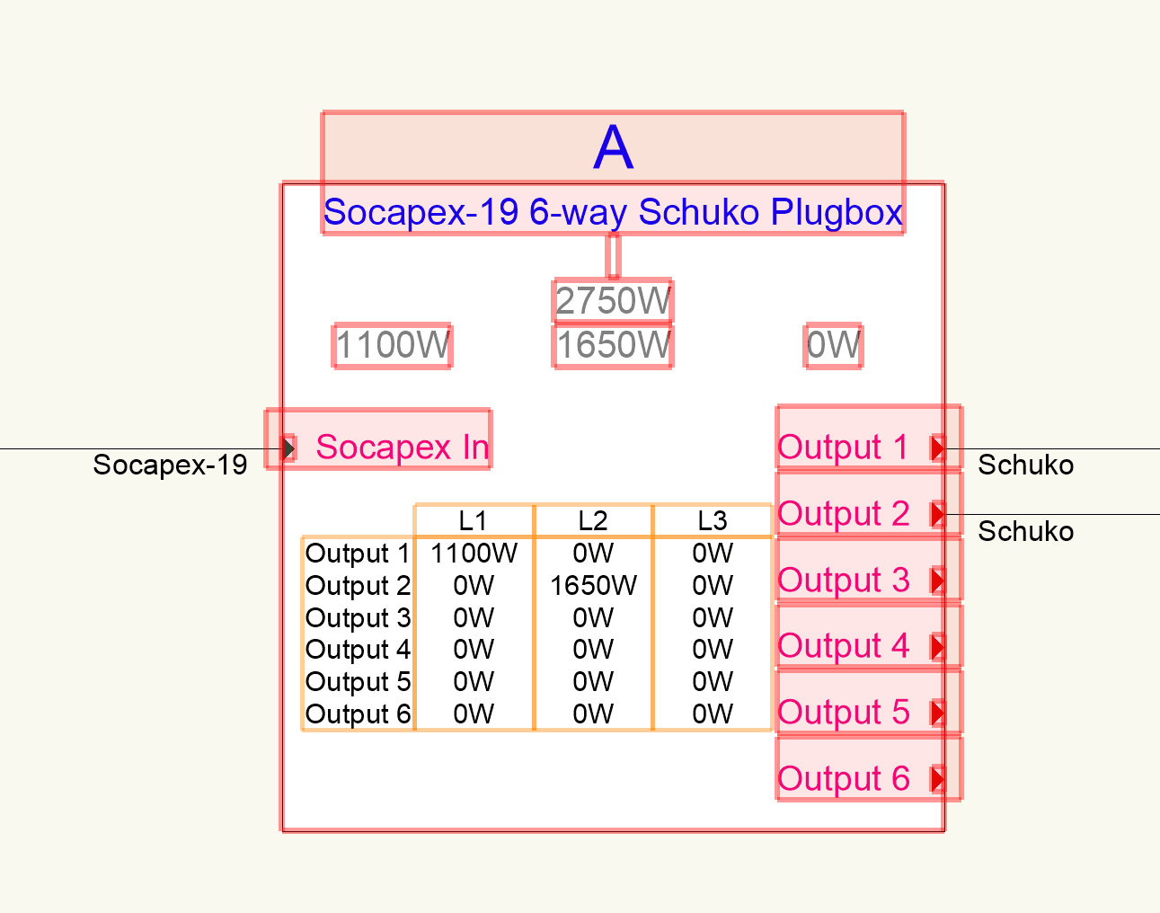
First, use Data Tags to display your breakout circuit loading. Start by selecting a schematic device using the Create Data Tag Style command. Add some active text for each phase and set it to use formulas.
You can copy the needed formula from the database column headers in the Spotlight Distributor Output Schedule worksheet in the Resource Manager. Then, set the tag to target output sockets in the criteria of the active text.
If you want to use break-ins or plug-tails, connect the first circuit with the Cable tool, then connect the rest in the power schematic.

You can also add Data Visualizations to your power schematics to display phase loading or positions. These visualizations make the schematic much easier to read for your on-site crew and collaborators. You can keep multiple data visualization schemes active simultaneously; just remember that the order you activate them determines the order in which they apply to your schematic.
The final step in your power planning process is providing all the necessary documentation to your on-site team and project partners.
The Spotlight library in the Resource Manager includes a set of worksheet templates that you can customize. One powerful technique is embedding multiple database reports in a single worksheet. For example, the Outputs report documents all input and output connections in a power schematic. If you customize the script to document a single breakout and then duplicate it using your standard breakout naming, you’ll generate an automated worksheet where each breakout appears individually documented.

Another useful technique is to preconfigure your worksheets. Integrate them with your starting template so the necessary classing and object naming come built into your file from the beginning. This setup helps automate your documentation and streamline your entire power planning process.
Learn More About Vectorworks Spotlight Workflows on Vectorworks University
To learn more about how you can leverage ConnectCAD features, check out Vectorworks University courses, such as:
BROWSE VECTORWORKS UNIVERSITY
VIEW COURSESStay in the know with the latest insights
Subscribers receive news, customer stories, success and learning tips, event information, and other important announcements from Vectorworks.
By submitting this form, you agree that Vectorworks, Inc. and its authorized partners may contact you in regards to news, offers, and the use of our software, services, and platforms. Learn more about our privacy practices and your data on our privacy page.*