
Detail drawings are the backbone of architectural documentation. They illustrate how individual components of a building come together, from foundations and walls to windows and roof assemblies. In the United States, they’re more than a best practice — they are a legal requirement. Without them, contractors are forced to interpret intent on their own, which leads to errors, cost overruns, and potential liability for architects if omissions create problems later.
WHAT ARE DETAIL DRAWINGS?
A detail drawing provides an expanded view of a specific part of a building at a larger scale than standard floor plans or sections. These drawings clarify connections that cannot be shown clearly at smaller scales, such as how a window jamb attaches to wall framing and finished faces or how a concrete slab ties into a foundation. They also indicate finishes, alignments, and tolerances that are crucial to the success of the construction. Importantly, the notes and annotations that accompany these drawings often carry more legal weight than the graphics themselves, which makes the written instructions just as essential as the visuals.
TYPES OF DETAIL DRAWINGS
There are three main types of details, each serving a different purpose.
Plan details: Plan details are horizontal sections through a building and viewed from above. They show how elements like thresholds or window jambs are configured in plan.

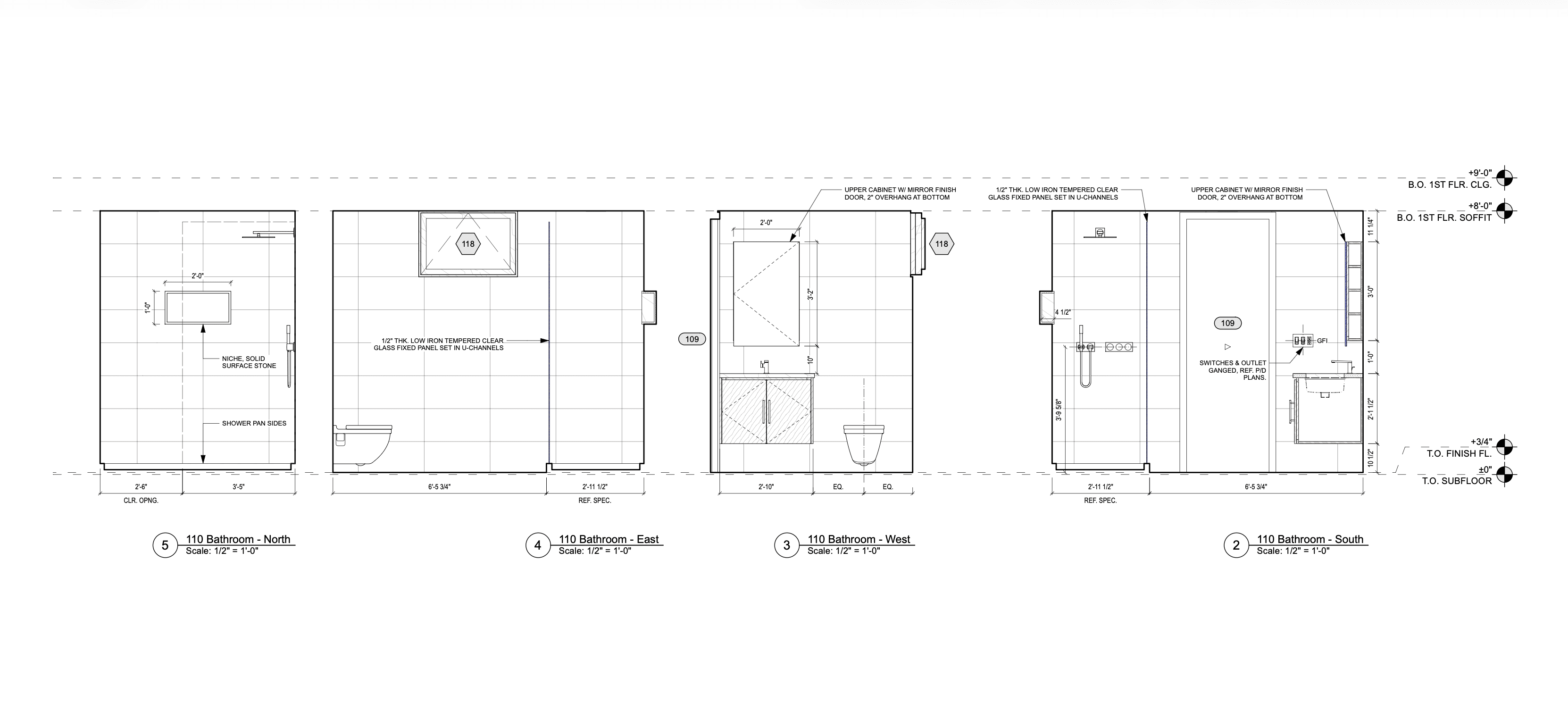
Elevation details: Elevation details present the flat view of one side of a building or building surface, highlighting finishes and materials.
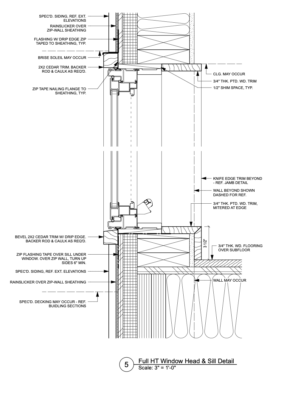
Section details: Section details cut through the building to show how assemblies come together, for instance where a wall meets a slab. These drawings are especially important in areas vulnerable to water penetration, but they can apply to any assembly where precision is required.

With these three types of detail drawings in your architectural toolbelt, you can effectively document any building element.
COMMON ELEMENTS IN DETAIL DRAWINGS
Although the scope of detail drawings varies depending on the project, most share a set of core elements that make them effective.
Building material information: Details specify exactly which materials are used — whether it’s concrete, brick, insulation, or sealants — and how those materials interact at points of connection. Materials are represented graphically and are supplemented with annotations, which are notes that add specificity.
Assembly and constructability information: Detail drawings describe how separate components come together — whether a slab meets a wall, a roof ties into parapet flashing, or a window is secured within its frame.
Compliance information: Compliance information: Detail drawings illustrate adherence to building codes, accessibility standards, and industry best practices. Beyond protecting the project team and end user, these details ensure the building is assembled to standard for lasting integrity and safety—covering fire separation requirements, insulation values, and waterproofing strategies.
Annotations: Notes often specify performance requirements, material standards, and installation techniques in ways that the drawn lines alone cannot communicate.
Connection information: Finally, detail drawings focus heavily on connection information. They clarify how parts of the building are joined — steel to concrete, wood to masonry, glazing to framing. These connections are frequently the most vulnerable points in a building’s envelope, especially where water, air, or structural forces are involved. Properly documented connections reduce the risk of failure and extend the life of the building.
CREATING DETAIL DRAWINGS IN VECTORWORKS
Vectorworks Architect offers an efficient workflow for creating detail drawings that combines accuracy with flexibility. Once you have your model, it’s easy to zoom into specific parts that need detailing. In other words, you don’t need to create detail drawings from scratch.
The Detail Callout tool allows you to select an area from a plan, section, or elevation and generate a larger-scale detail viewport. Drafting directly over the 3D model helps ensure that details remain consistent with design changes, which ultimately reduces errors.
The Detailing tool palette includes ready-made 2D symbols such as joists, insulation, and anchors, saving time in production. You can also build reusable symbol libraries, standardizing details across projects and streamlining documentation. These reusable symbols will be saved to your Resource Manager for use again and again.
Detail Drawings: Vectorworks Architect vs. AutoCAD & Revit
Compared to AutoCAD, which relies on a color-based system for line weights and can feel less intuitive, Vectorworks provides a true what-you-see-is-what-you-get interface that makes drawing more straightforward and visually accurate.
Compared to Revit, Vectorworks Architect is a CAD and BIM program; this dual focus gives you greater freedom and flexibility when working on 2D details than the rigidity inherent to Revit.
Stay in the know with the latest insights
Subscribers receive news, customer stories, success and learning tips, event information, and other important announcements from Vectorworks.
By submitting this form, you agree that Vectorworks, Inc. and its authorized partners may contact you in regards to news, offers, and the use of our software, services, and platforms. Learn more about our privacy practices and your data on our privacy page.*