
Section drawings are essential tools for understanding how buildings work from the inside out, communicating both design intent and construction execution details. These vertical cut-throughs expose the internal anatomy of a building, offering insights that floor plans and elevations alone can’t provide.
This article breaks down what section drawings are, the different types you’ll encounter, why they matter at every phase of a project, and how tools like Vectorworks Architect streamline the process of creating sections.
What Are Section Drawings?
Also known as cross-sections, section drawings are architectural visuals that reveal a vertical cut through a structure. This cut exposes information not readily apparent in standard plans or elevations making them indispensable for visualizing vertical espatial relationships, material layers, and construction techniques.
Types of Section Drawings
Not all section drawings serve the same purpose. Each type plays a distinct role in guiding both design decisions and construction.
Building Section Drawings
The most common type is the building section. This drawing slices vertically through the entire structure, often from foundation to roof, to reveal the building’s internal organization. It highlights how different floors relate to one another, how structural systems interact, and how spaces stack or connect vertically. Building sections are often used early in the design process to refine proportions, ceiling heights, and circulation paths, but they also remain essential during construction to show how everything fits together at scale.

Wall Section Drawings
Wall sections take a closer look at a specific wall assembly. These drawings dissect the wall from the inside out, showing layers such as insulation, vapor barriers, sheathing, framing, cladding, and finishes. They often extend vertically from foundation to parapet or roof edge. Wall sections bridge the gap between architectural design and construction detail — they show how the wall performs structurally, thermally, and aesthetically. Contractors rely on them to understand how different systems integrate within a confined slice.

Detail Section Drawings
Detail sections are the most granular. They focus on critical construction junctions like membrane overlaps, flashing conditions, floor-to-wall interfaces, or how a window frame embeds into a wall. These drawings are usually enlarged to a scale that clarifies every component and connection. Detail sections are an architect’s visual instruction manual for construction professionals — they eliminate guesswork by showing precisely how elements are to be joined, fastened, sealed, or aligned.

The Benefits of Section Drawings
Section drawings deliver unmatched clarity by exposing the internal makeup of a building in a consolidated view. They help architects and engineers see how floors, walls, ceilings, and structural components come together. This level of transparency is for effective design communication as well as legal and code compliance, including height restrictions, fire-rated assemblies, and waterproofing requirements. Their ability to show so much information at once has earned sections a reputation as the most informative drawing type available.
Beyond the technical, section drawings bridge the gap between professional teams and clients. Rendered or stylized sections can visually communicate complex interior layouts and spatial relationships in ways that floor plans or elevations simply can't.
Across the entire project lifecycle, section drawings maintain their value. In the early stages, they clarify how a building interacts with its site, how spaces are organized vertically, and how people will move through the structure. As the project shifts to construction, sections provide the precision needed to build accurately and meet regulatory standards. They’re not only helpful — they’re required elements in permit applications and official construction documentation.
DISCOVER THE TRENDS SHAPING THE AEC INDUSTRY
Vectorworks talked to hundreds of architects, designers, and others to see what technology trends are shaping the future of the AEC industry.
Creating Section Drawings in Vectorworks Architect
Vectorworks Architect is a design and BIM program purpose built for delivering constructible architecture projects. When it comes to section drawings, the software simplifies creation with smart coordination between drawings and model. You can use tools in Vectorworks to generate section drawings derived directly from the model, which eliminates the need to manually draw sections — additionally, because of this coordination, updates to your model automatically reflect in associated section drawings.
Let’s take a look at these tools and some key considerations to keep in mind when creating section drawings.
Considering Scale, Detail, and Purpose
As you progress from building sections to detail sections, the level of detail (LOD) becomes increasingly specific. The more detailed the section, the more critical it becomes for construction precision. Keep this in mind as you develop sections — there’s a key distinction between technical sections, used for construction purposes, and presentation sections, created to communicate ideas to clients or non-technical audiences. Presentation sections may feature perspective views, shading, depth effects, or even textures and colors to better convey the spatial experience of a design, while detail sections are more likely to be created in 2D for technical precision.
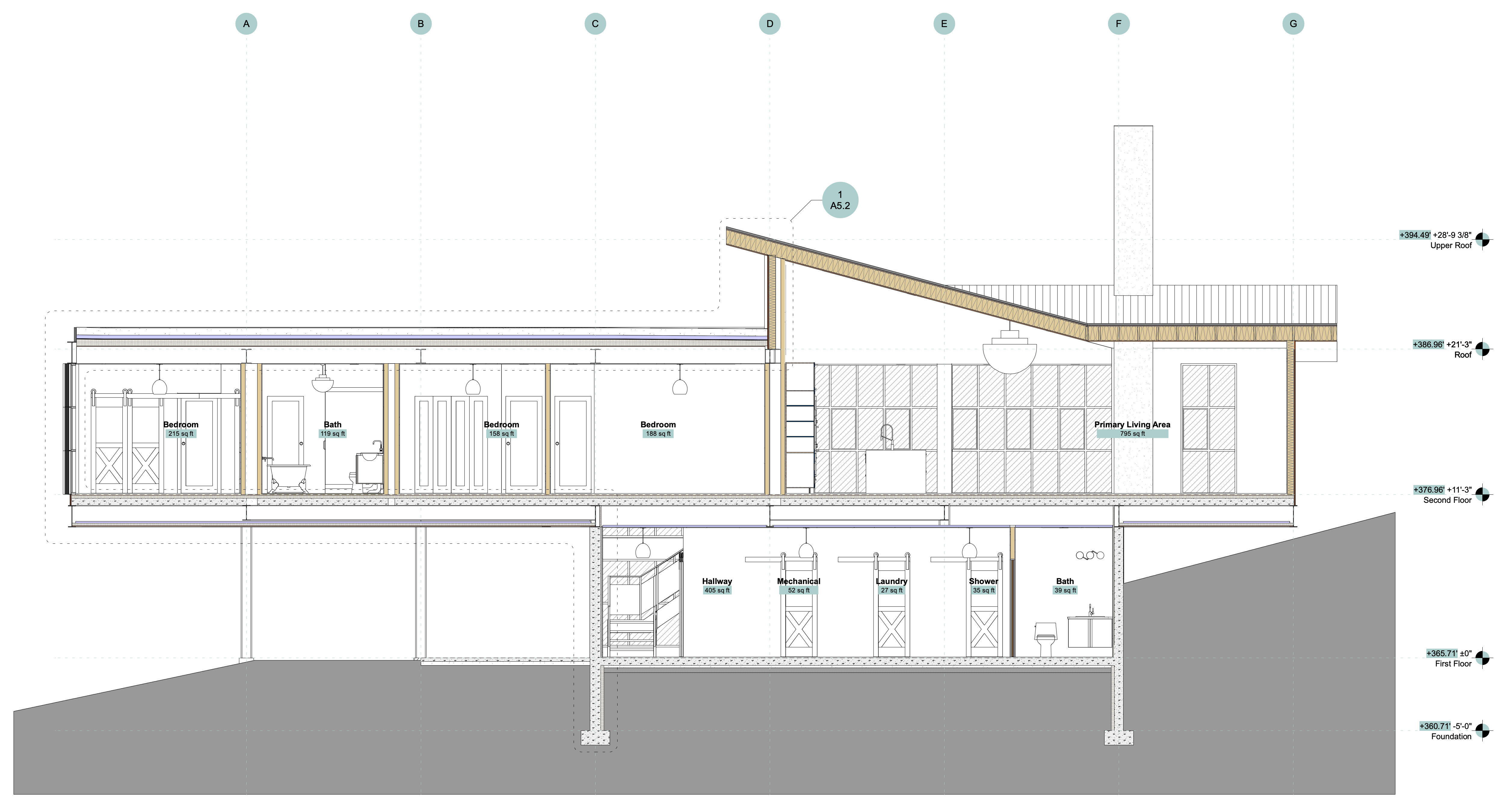
A traditional 2D technical section drawing.
In Vectorworks Architect, you can swap between presentation-style sections and technical, construction sections quickly via the Object Info palette in a Viewport. If you plan on using perspective, presentation-style sections frequently, you can set up a Viewport Style — which you’ll read more about later in this article — ahead of time to be ready for you to use when you need it.
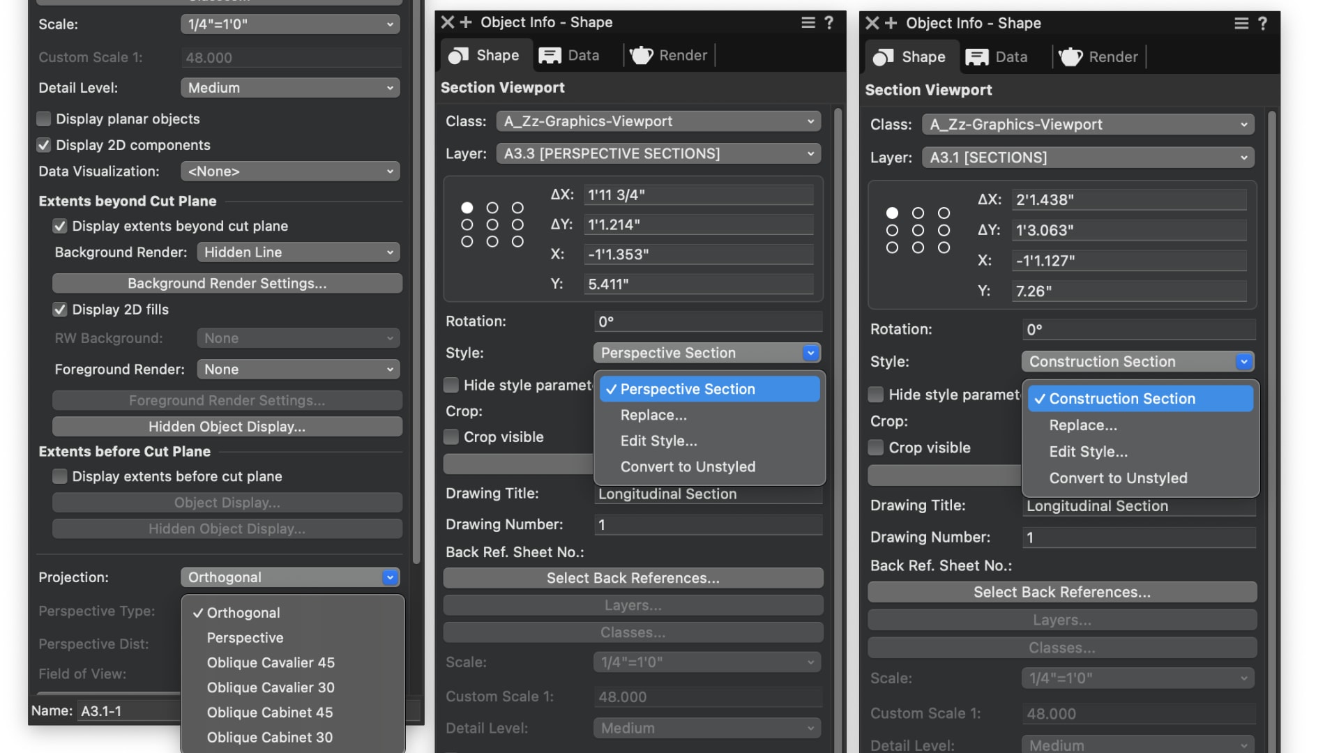
Object Info palette settings showing how to switch between perspective and construction sections.
The Clip Cube Tool
The Clip Cube tool enables interactive visualization and creation of section views, making it particularly useful during design and presentation phases alike. The tool functions by temporarily “clipping” away pieces of your model — doing so allows you to explore design options during schematic phases and, later, quickly produce sections with just a few clicks.
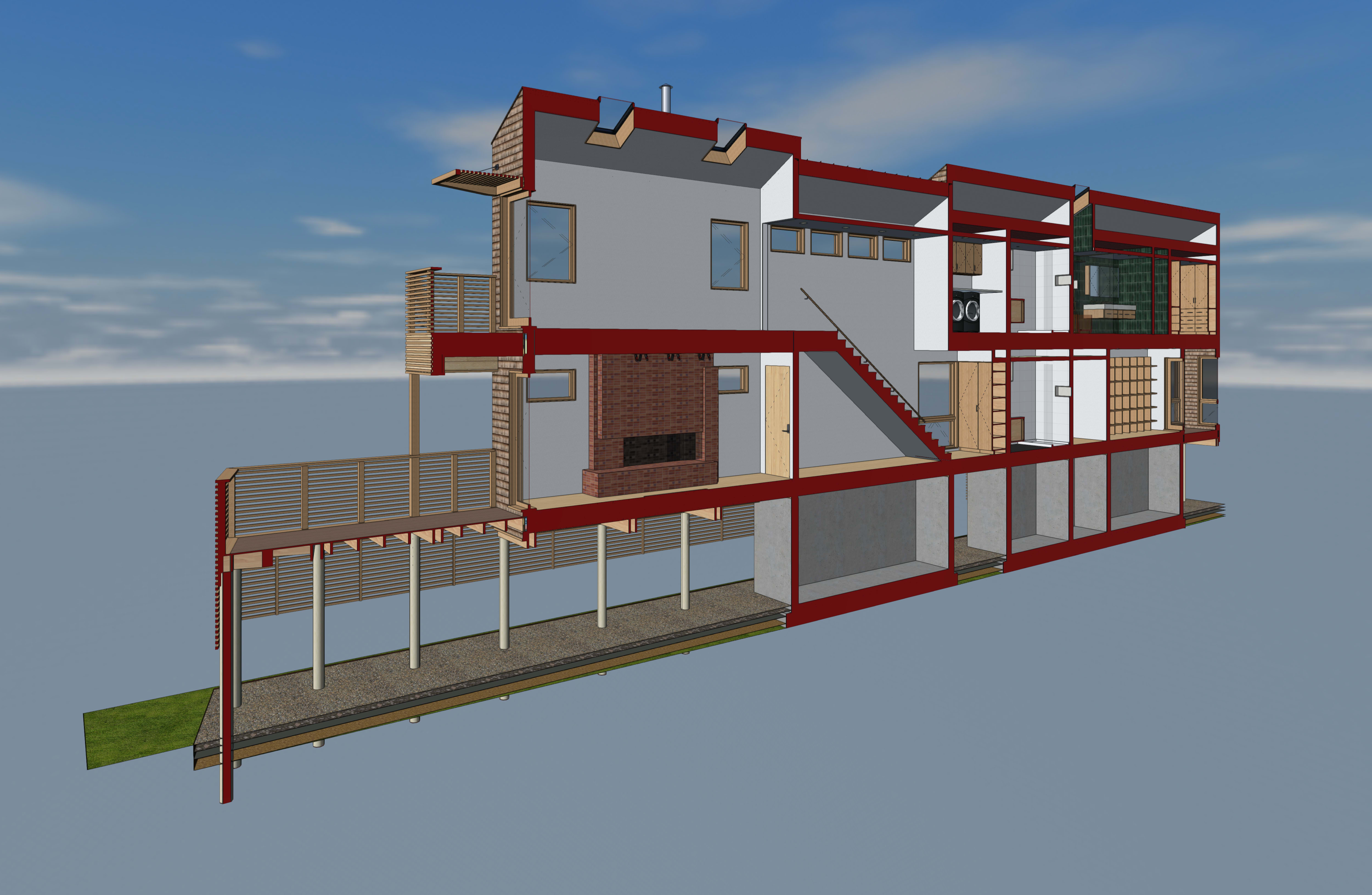
A stylized perspective section created with the Clip Cube tool.
Viewports
Functionally, viewports are dynamic windows into your drawing or model. They allow you to display specific views, details, or sections on dedicated sheet layers for printing, presentation, and coordination.
For the purposes of creating sections, there’s a dedicated Section Viewport feature that allows you to generate section drawings directly from the model, offering precise control over cut planes and viewing depth. For more granular detailing, the Detail Viewport feature lets you zoom into specific areas while maintaining coordination with the overall model.
Viewport Styles
You have the option to set up your intended viewports before you even begin designing. Taking advantage of Viewport Styles allows you to define elements such as annotations, dimensions, render styles, and title blocks ahead of time so that when it comes time to cut a section, you can place it in a viewport that’s already most of the way to your desired result.
A common way to customize the appearance of objects in viewports is to use Class Overrides. Overrides only affect the viewport in which they’re set, leaving the original class attributes unchanged in the model itself, making this a valuable option for further customizing Viewport Styles.
Stay in the know with the latest insights
Subscribers receive news, customer stories, success and learning tips, event information, and other important announcements from Vectorworks.
By submitting this form, you agree that Vectorworks, Inc. and its authorized partners may contact you in regards to news, offers, and the use of our software, services, and platforms. Learn more about our privacy practices and your data on our privacy page.*