If you’re looking for information about framing workflows in Vectorworks Architect, you’ve come to the right place.
Understanding the powerful structural tools in Vectorworks allows you to design precise timber, steel, or mixed-material structural systems that are fully integrated with your 3D model while simultaneously generating reports on quantities for cost estimations.
STRUCTURAL MEMBERS VS. FRAMING MEMBERS
Structural Members
Used for principal load-bearing components such as beams, columns, and girders. These tools are parametric, allow complex joins and shapes, support various material assignments, and provide deeply customizable documentation. The tool embeds data for easy generation of schedules and quantity reports.

A Vectorworks model with a structural member highlighted.
Framing Members
These tools are suited for simpler, secondary structure modeling, but support both standard and custom shapes, including trusses and open web joists.
KEY WORKFLOWS FOR STRUCTURAL SYSTEMS WITH VECTORWORKS ARCHITECT
To get started with these workflows, you’ll need to have a basic building shell model of walls and/or roof objects. From there, follow these steps.
Wall Framer Workflow
Open the Wall Framer Tool: Go to AEC > Framing > Wall Framer… in the Vectorworks menu.
Set Up Layers and Framing Options: Choose the layers you want to create framing for. Define the type of framing you want to generate — such as studs, plates, sills, headers, and blocking.
Select Framing Preferences: Pick the framing size you need. Choose whether to create a 2D representation, a 3D model, and/or quantity reports.
Generate the Framing Model: The tool automatically creates detailed timber wall framing directly from your existing wall geometry.
Best Practice: Apply this workflow at the right time. Use this process after wall layouts are finalized to ensure accurate framing representation.

Wall framer model in the background with settings in the foreground.
Create Joists Workflow
Access the Command: Go to AEC > Framing > Create Joists…
Define the Geometry: Select an existing slab or draw a polygon to use as the base for the joists.
Set Joist Parameters: Define spacing, shape, material, and class. The command automatically spaces joists for consistent framing.
Generate the Joists: The tool quickly creates framing members, removing the need for manual spacing.
Best Practice: Again, use this workflow at the right time — later in the design process, similar to when you do other framing workflows.
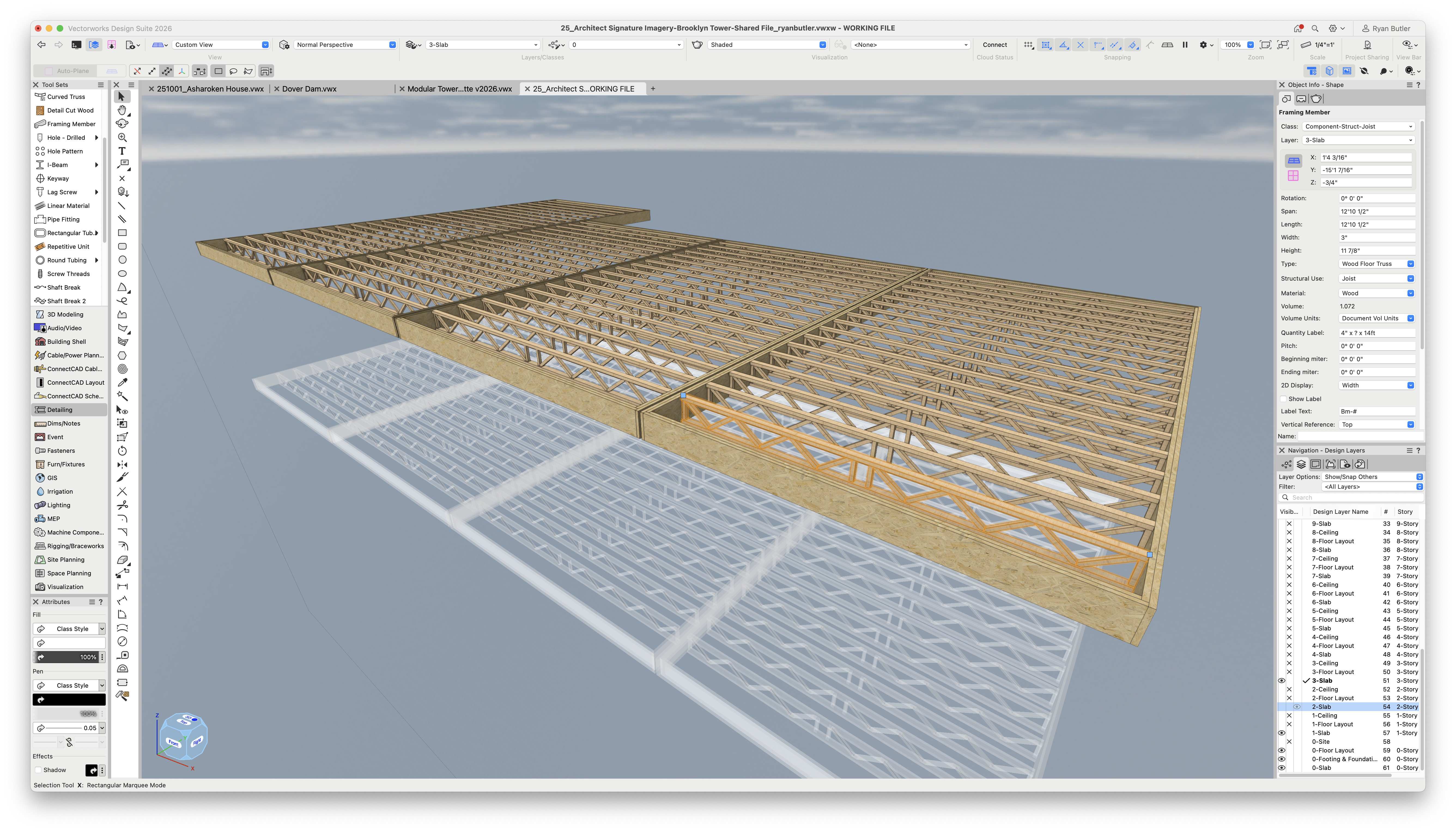
Framing members in a slab, created with the Create Joist command.
Roof Framer Workflow
Open the Roof Framer Tool: Go to AEC > Framing > Roof Framer…
Select Roof Objects: Choose the roof geometry you want to frame.
Configure Framing Options: Define the member sizes and spacing for elements such as rafters, collars, plates, purlins, ridges, headers, and hips/valleys.
Generate Roof Framing: The tool automatically creates the framing model using either standard or custom-sized members, spaced according to your settings.
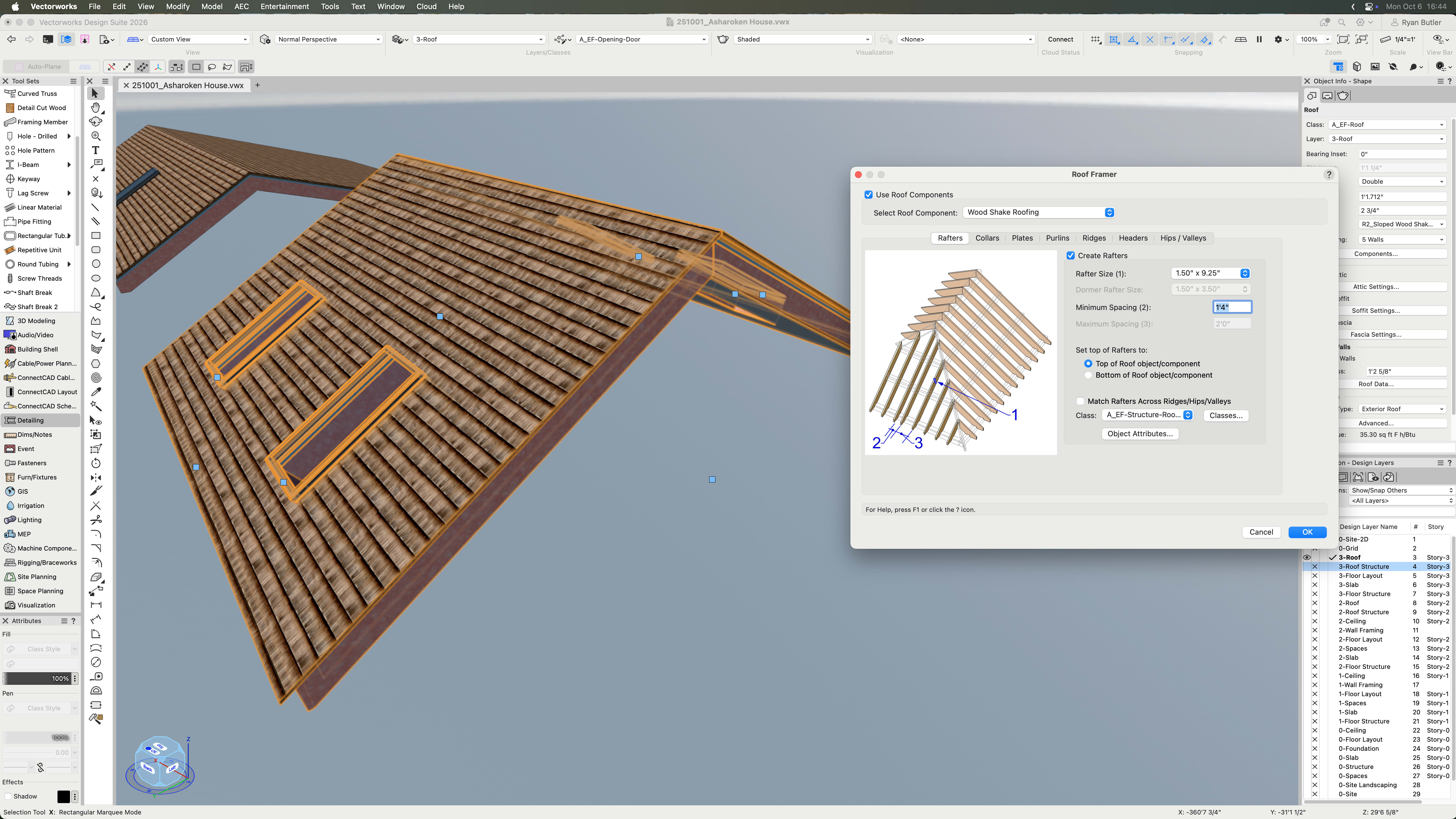
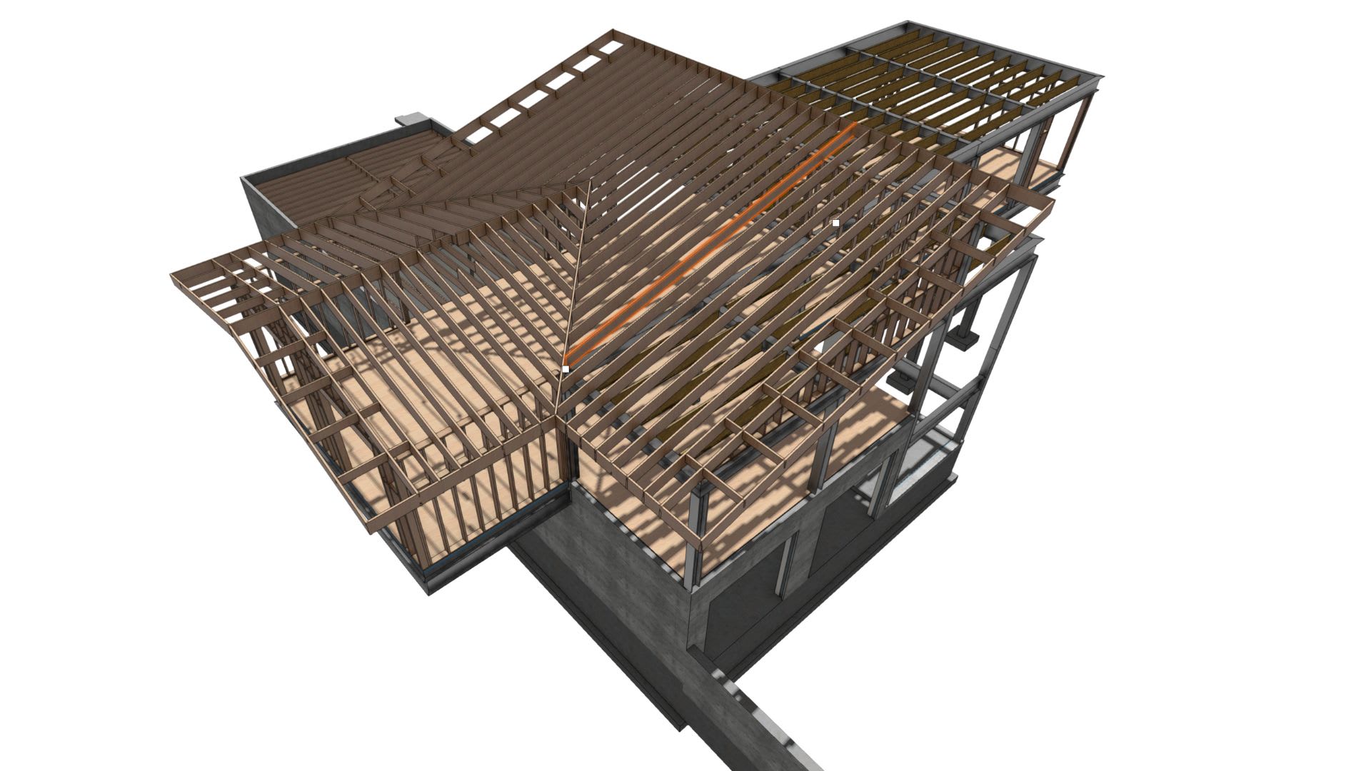
A roof with Roof Framing settings in the foreground.

The resulting roof framing.
DOCUMENTING STRUCTURAL SYSTEMS
As you may know, the fact that Vectorworks Architect has parametric modeling tools means you can easily pull data from geometry for reports. There’s no creating documentation from scratch — once you create the geometry, you can document it near automatically.
If you’re looking for a more comprehensive resource on designing full projects with Vectorworks Architect, check out the presentation linked below.
Stay in the know with the latest insights
Subscribers receive news, customer stories, success and learning tips, event information, and other important announcements from Vectorworks.
By submitting this form, you agree that Vectorworks, Inc. and its authorized partners may contact you in regards to news, offers, and the use of our software, services, and platforms. Learn more about our privacy practices and your data on our privacy page.*